Updates to the COMPASS system since first publication
The problem: static descriptions of an ongoing project
The original paper in Wellcome Open Research was based on Open cross-platform software and interactive notebooks. This was mainly to encourage people to understand it was not immutable, or even as useful as it could be.
Keeping the first description simple was also important to allow an actual scientific publication (The Wellcome Open Research/F1000 platform also helped with this process, in a way that traditional publishers maybe couldn't).
The following pages detail how the COMPASS project is being developed since publication and suggest alternative setups that might work better for some people.
With the process of writing the first paper came some uncertainty as to how far people would wish to go in making their own equipment. In addition is always the question, can you methods actually be followed. Although this has always been the claim of the 'methods' section of all scientific papers, in many cases this has been (sadly) far from true. If the current drive to define what Open and reproducible science should be in the future, moving away from methods as an inconvenience/afterthought has to be central to this.
Feedback, and important corrections and improvements would be very welcome. It you use it please let me know / cite our original paper. Thanks
Further details on hardware choices, circuit boards and cases:
1. Planning to build the system
Some assembly required...
When we started the project, we had a couple of aims: to introduce passive infrared sensors to our existing system for monitoring activity and to explore the possibility of being able to make a simple device with which we could ask others to look at patterns of activity in their laboratory mice. The COMPASS system came out this process.
The sensor chosen (Panasonic AMN32111) has several components integrated (including a digital amplifier), to ensure the function will be as consistent as possible between sensors/cages. This allows the rest of the system to be flexible and low-cost, while remaining easy for someone to build, even if new to microcontrollers and programming. Even so, it will be more suited to those who know one end of a soldering iron from the other (you won’t forget twice), or find someone who self-identifies as a ‘maker’ to provide encouragement.
The open nature of the system means you are actively encouraged to consider modifications and improvements. There are clearly a number of things that might suit your lab better (more channels, other sensors, storage options), but if you hope to use immobility as a correlate of sleep in mice you will need to keep the sensors at less than 22cm from the cage floor, ensure that the full area of the cage is detected by the sensor and have singly housed animals. Otherwise new EEG recordings alongside the actigraphy will be needed to confirm the validity with the modified system of the assumption that >40sec of immobility is sleep.
Other considerations when building a system would include:
Ensuring that sensors are stable and secure:
moving sensor + static animal == static sensor +moving animal.
Preventing gaps in data due to loss of power:
laptop batteries help here, as the whole system is powered from USB ports. Alternatively, a range of uninterruptable power supply (UPS) devices are available, including some for the Raspberry Pi (like PiJuice.
Automatic restarting on loss of power:
covered in the Node-RED setup below.
Positioning of sensors, microcontrollers and computers for recording:
sometimes there is a simple place to put a laptop, a small board PC like the Raspberry Pi might be perfect if collecting data in an animal house.
Remote access:
SSH and remote desktop options will allow you to check on and collect files.
A full detailed set of building instructions will be generated if required, so please get in touch if you are interested.
2. Bill of parts/materials(Arduino 6-channel)
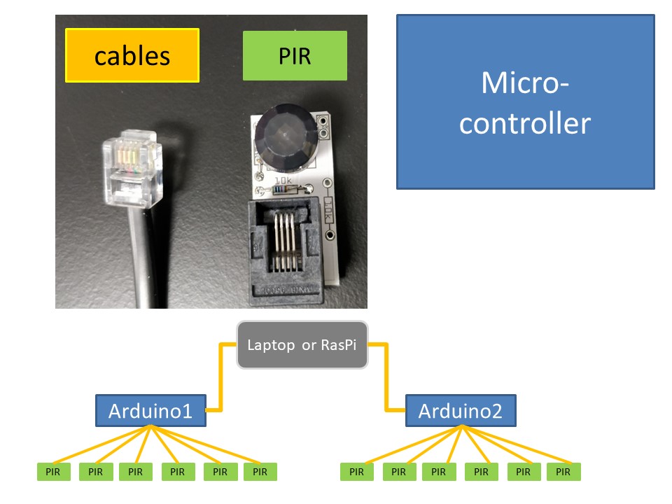
Different components of the COMPASS system, color coded to match the bill of parts in the table here. A single laptop or Raspberry Pi (GREY) can be used to run multiple microcontrollers (such as an Arduino, BLUE) and each Microcontroller will be polling multiple sensors/cages (GREEN)
parts list HERE, or as .CSV file for download. Numbers of part are for a 6 channel system, but some parts may have a minimum order and you may want to consider spares.
Codes listed are for Onecall/Farnell, but most or all should be available from Mouser and RSonline, amongst others.
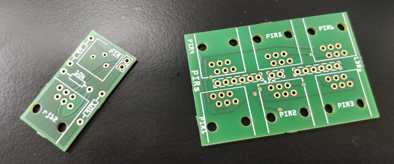
3. Circuit boards
i. Fritzing / Aisler :
The original paper was accompanied by files for the 2 type of circuitboard used in the COMPASS system; The main board on the Arduino microcontroller and the small boards of the PIRs and optional LDR.
The software used for this was (again) and open-source project called Fritzing. Currently the easiest way to get these boards is to use the main manufacturer for Fritzing, which is Aisler. The files are available as links here (main board) and here (sensor board). Further designs will be added here and on GitHub after they have been tested.
ii. Alternatives :
The Fritzing software allows output of a number of formats if you have particular requirements or have to use certain suppliers.
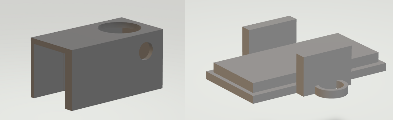
4. 3D models for PIR cases (.stl files for case and lid)
A range of cases and containers can be fashioned for holding the sensors. Bare boards could also be mounted above cages, but care should be taken with alignment and protecting the sensors from damage.
One option for 3D printing is provided here, if you have access to a 3D printer.
STL file for PIR box and the STL file for lid
5. Building Tips (some infomation updated from the Suppl. file1 in the paper)
a. Assembly of components
Positions for 1k resistors and 10k resistors are clearly marked on the boards.
There is a space to solder either a 2‐pin header or an LDR directly to any of the breakout boards for the PIRs. If using this option, solder and additional 10k resistor to that breakout board.
The sketch for the Arduino is written to expect a single LDR, to be connected to analog pin2.
Right‐angled RJ12 connectors were used for the breakout boards for the PIRs, as this offers better options for positioning cables. Vertical RJ12 connectors were used on the base unit for the same reason.
b. Soldering tips
A number of guides are available, this is a nice one, the mightyohm.com soldercomic
c. Calibration and common problems
- Not acquiring the Arduino microcontroller board after plugging in:
- a. Check Arduino IDE is open.
- b. Attach board by USB cable
- c. Check >Tools menu for correct >board and >port entries
- d. If this fails, unplug microcontroller, and plugin again
- No readout or file saved after running the sketch in Processing:
- a. Close Arduino IDE
- b. Run Processing Sketch again
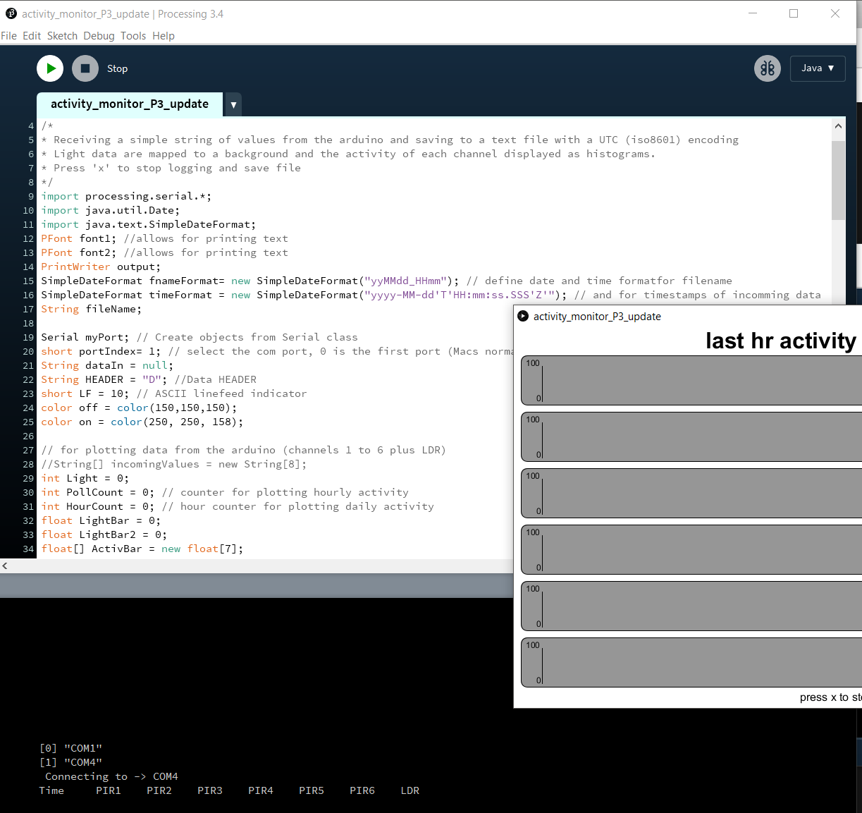
- c. The program puts out a list of available serial ports at start up (in black panel at the bottom), with their assigned indices.
- d. If the histogram window does not appear, the program will be looking for incoming messages from the wrong port. This is solved by changing the ‘portIndex1 =’ value towards the top of the processing sketch and trying again.
- Unexpected readings:
- a. Floating random values (ungrounded pin, normal if not sensor is connected).
- i. Check cable and sensor (try new ones). Incomplete circuits, usually due to soldering errors.
- ii. Check connections on the main board and that the board is connected correctly to the pins on the Arduino microcontroller.
- b. Constant readings of ‘0’ or ‘100’ :
- i. If on all sensors, problem is probably with main board or microcontroller (disconnect all cables one by one).
- ii. Ensure RJ12 cable does not cross‐over (see cables section)
- iii. On single sensors replace cable and or sensor until problem is identified. If still faulty check connector on main board and jumper wire from main board to microcontroller.
- c. Problems with reading environmental light:
- i. Pointing the face of the LDR towards the light source can improve the range of values in light and darkness
- ii. Ensure legs of the LDR are not crossed and touching. This will short circuit (bypass) the resistor leading to constant readings of 0.
Setting up and running COMPASS using Node Red on a Raspberry Pi.
1.Hardware
The bill of parts above has a link to one of the starter kits for the most recent Raspberry Pi kit (including board, case, power supply and a suitable SD card with Raspbian operating system already installed. These are available from many places and are by far the easiest way to get started. In addition to these items you would need an HDMI-capable monitor (or adapter) and keyboard and mouse to get started (even if you plan to run the Pi remotely later).
2.Software and setup
There are dedicated pages for setting up Node red on the Pi. The default Raspbian operating system already had node red installed and the details for updating are straightforward.
3.Additional Node types and COMPASS Flows
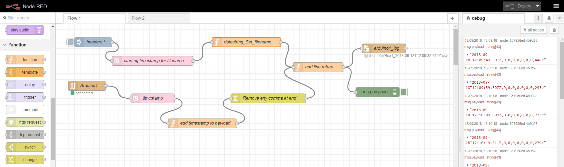
Once the web interface for Node Red is available the other nodes you will need can be installed via the 'manage pallete' option on the web page. The additional nodes required are:
- thethingbox-node-timestamp
- node-red-node-dropbox (if planning on this method for remote backup)
The next step will be to import the flows needed to collect the data from a connected Arduino (and potentially to back this data up). The main flow can be found on the Node-RED website, as COMPASS_Arduino string to .csv. An additional flow for backing up the .csv files to DropBox can be found here too, as COMPASS_backup to Dropbox.
Setting up and running COMPASS and Processing(3.x)on a Raspberry Pi.
1.Hardware
As for the Node Red option above. There is also a premade disk image of Raspbian with Processing 3 installed (although the install script worked fine for me.)
The assumpiton will be made that an old laptop or Raspi will be used to collect data, using a basic monitor, keyboard and mouse. If you are planning to run a Raspberry Pi in 'headless' mode (without monitor and peripherals) you will probably need to use node red.
2. Setup
A wealth of detail specifically for the Pi is provided at https://pi.processing.org/. The Processing website also contains helpful references guide to the language and forums.
3. Sketch
The WOR paper was publishes with a sketch (program) that ran on Processing version 2.2.1. As version 3.x is under active development and has introduced a few changes, I have updated the sketch, currently working with v.3.4. This can be downloaded HERE and soon on Github. As described in the paper, the sketch needs to be opened from within Processing program and then run (press play). Look to the console and errors below if anything fails to happen.
Current Project Status:
COMPASS Nodered
Processing3 sketch on Raspi
Real-time analysis
Relevant Links
Some sites related to the COMPASS project.