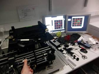
Open Microscope Alignment
Paul Barber, Iain Tullis, Boris Vojnovic, April 2011.
Contents
Bottom Mirror and Optical Path
Bottom Mirror and Optical Path
|
1) Make sure base is square on the table. |
|
|
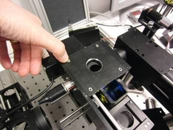
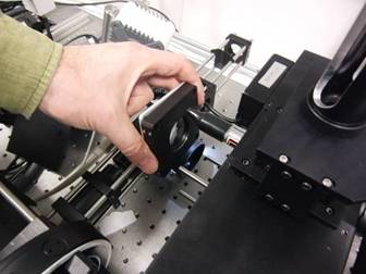
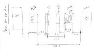
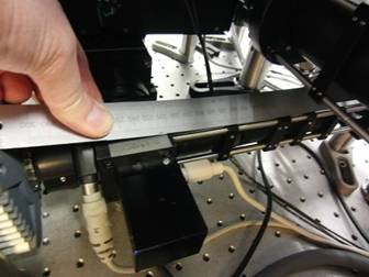
2) Bottom mirror (BM) + mirror switch (MS or optical path) alignment with tube lens removed. Check by eye that BM is roughly square with optics, or remove MS arm and use a target directly at side of BM. Remove camera and use 2 t-shirts (TS) with large and small holes in camera arm (CAM). Use aperture (AP) in-situ and TS in laser scanning (LS) arm. On top of BM block use 2 separated AP’s.
|
|
|
By eye align all apertures and targets with BM and MS offset adjustment. Iterate CAM and LS arms. |
|
|
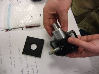
3) Assemble cube slider (CS) onto BM block. Check post heights. Remove cube slider and measure posts if necessary, they can vary be should be correct at manufacture. |
|
|
4) Use jig to set alignment of z stage (ZS). |
|
|
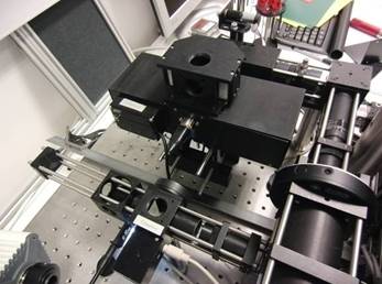
5) Assemble and then test alignment through CAM and LS arms as in 2. |
|
|
6) Insert tube lens. May have to un-assemble tower and slightly lift it up to get all tube lens components in place. Align again as in 2. |
|
|
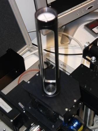
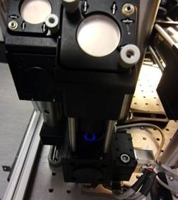
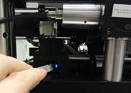
Replace camera. Place target on top of tower and illuminate (close down the AP below it in the alignment tool). Can now align target at image centre, but also check LS arm by replacing target with AP as in 2. Iterate CAM and LS arms. Can add piezo z drive now and check alignment again. |
|

Fluorescence Excitation Arm
|
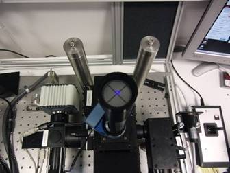
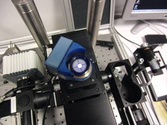
7) Fluorescence (FL) excitation alignment. Adjust apertures to get a small spot at the top of the tower. Use the following 3 steps to check alignment. |
|
|
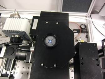
With target on top of tower, check centrality low, at the objective (OBJ) position. |
|
|
… and high on the alignment tool. |
|
|
Add an objective and balance a FL block on it. View this epi spot on the camera – it should be central. |
|
|
The only real adjustment here is to fiddle with the prism mirror under the cover. This can be rotated and pushed back and forwards. |
|
|
Bingo! |
|

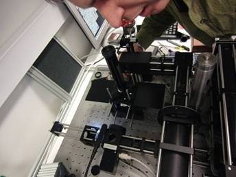
FLIM Laser Alignment
|
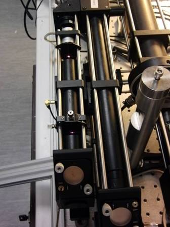
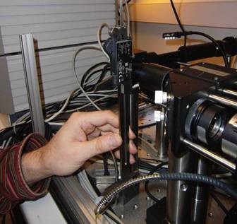
8) Align laser through the telescope section with the first lens (L1) and pinhole (PH) removed. Have tip/tilt and y adjustment from top mirror (M2). Can get some extra y by loosing and fiddling with the bottom mirror (M1). X adjustment must come from loosening the laser fibre coupler and fiddling with that. Insert L1 and PH and check alignment again. |
|
|
9) Align past the dichroic/beam splitter (BS) with the post telescope mirror (M3). Only tip/tilt and x should be required here (that’s all you have!). |
|
|
10) Check rough laser collimation past the telescope by running a card up and down the beam that comes out of the ‘wrong’ exit from the BS. Here, the beam has been turned by a make-shift mirror to get a long path. |
|
|
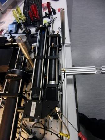
11) Alignment onto S1 through AP2 with M4. In practice AP1 is set at 6 mm. |
|
|
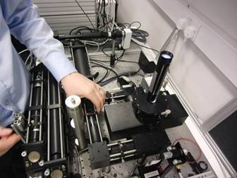
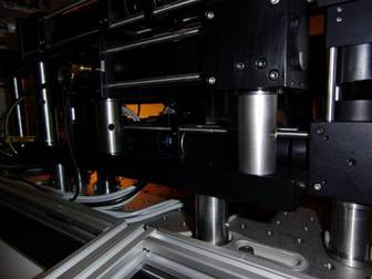
12) Align through 4f system onto S2 with beam parked centrally (set software scanner offsets to 0,0). Can tweak M3 (post telescope) for alignment through AP2 and M4 for alignment through slit (AP3) in the middle of 4f system (shown here). May need to loosen scanners and twist for rough alignment and so edge of beam does not clip. |
|
|
13) Check position of scan lens after S2. If these are correct with a focussed beam at the intermediate image plane (AP4) then we should be getting light up at the objective.
|
|
|
|
|
|
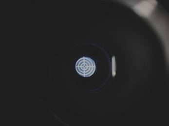
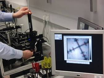
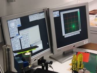
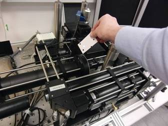
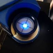
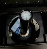
14) Check it is central, straight up and collimated (roughly) out of the objective holder. NB The beam shown left is too small (maybe pinhole too large) and is also clipped at the bottom by a scanner. You should only see the central Gaussian-like beam overfilling the 15 mm aperture (as picture right). |
|
|
15) Scan Very Fast at 64x64 with scanners reversed (scanner settings panel) to check beam is stationary on S2. May need to remove a rod and shields after S2 to see it. Tweak the position of the 4f lenses symmetrically to get it stationary Un-reverse scanners and check beam is stationary at the objective back aperture with the Nikon FL alignment tool (or a target on 8 mm tube + RMS adapter). |
|

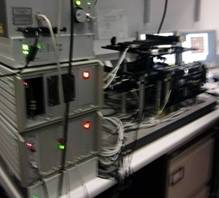
PMT Arm
|
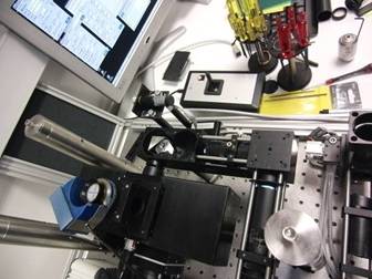
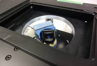
16) Check the height and rough alignment of the PMT arm. |
|
|
17) Laser off. Look back down the PMT arm at an illuminated target and adjust the PMT arm steering mirror. |
|
Final Image Registration
|
18) Assemble stage etc. and image a sample with FL. Image with SPC/FLIM and tweak telescope collimation of laser for parfocality with FL (Make sure FLIM is focussed in the same plane as FL). |
|
|
19) Check scanner Lag Compensation by getting an image at the slowest setting, noting the position of something in the image, and then scan fast. A horizontal shift indicates top pot should be adjusted. 20) Adjust FLIM field of view to be same as FL using the software scanner offsets for x,y shift and the two lower hardware pots for x,y scale. |
|