Colorimetry
Recently, I have been working on colours of the solar system planets. This colorimetry page is based on Appendix A of our recent paper Modelling the seasonal cycle of Uranus’s colour and magnitude, and comparison with Neptune.
Colour-Matching Functions
The response of the human eye to colour is reviewed by Stockman et al., (2019), which I will summarise here. The colours are perceived by the cone receptors of the human retina, which are divided into cones sensitive to short, medium and long wavelengths across the visible spectrum. The standard definitions of the response functions for these S, M, and L is defined by the Commission Internationale de l’Éclairage (CIE) (http://www.cvrl.org). The CIE define the spectral responses of am average human eye, regarding either a 2° or 10° field of view, with the 10° responsivities, l10(λ), m10(λ) and s10(λ), now held to be 'standard', and shown in the figure below}. When regarding a coloured object the visible spectrum stimulates the three cone types differently, giving a 'tri-stimulus' response that the typical human eye then perceives as colour. Since the cone sensitivities have broad wavelength responses, it is quite possible for humans to perceive two distinctly different flux spectra F(λ) as having the same colour.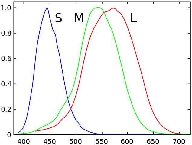
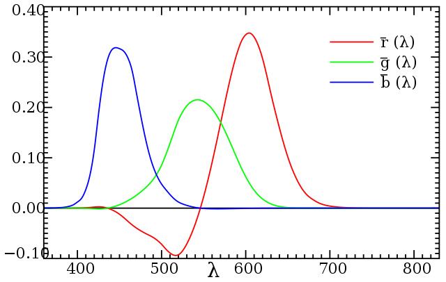
The colour of a real object is simulated on a computer monitor as a combination of three different distinct RGB colours (red, green, blue), or in print media via the CMYK system (cyan, magenta, yellow, black). For computer monitors the RGB pixels are usually narrow-wavelength bands centred on 645, 526 and 444 nm, but there is considerable variability between different devices. To try to standardise the treatment of colour in computer devices, Microsoft and HP defined the standard RGB system (sRGB) in 1996, which is now the standard colour space used by most computer devices and also the World-Wide Web. To represent the colour of an object in sRGB we need to determine the correct combination of RGB that gives the same tri-stimulus response as the actual object would to the human eye. This is done, for monochromatic wavelengths, by filling one half of an incident field of view with light of a test wavelength and then filling the other half with a combination of R, G and B and adjusting the relative brightnesses until both halves appear the same to an 'average' human observer. For many wavelengths, this is possible with positive brightnesses of R, G and B, but for some wavelengths it is necessary to add one RGB colour to the test wavelength and then balance with the other two. In other words we need a negative contribution from one of the RGB colours. Wavelengths for which this happens are said to be 'out of gamut' and cannot quite be simulated with sRGB. The resulting functions that relate the LMS to RGB responses for monochromatic test colours are called the Colour Matching Functions (CMF).
Because of the non-standard nature of RGB systems and also the fact that it is not quite possible to reproduce all LMS responses with positive contributions of three individual narrow colours, the Commission Internationale de de l’Éclairage have defined the XYZ colour space, for which the colour matching functions (available at http://www.cvrl.org) are positive at all wavelengths.
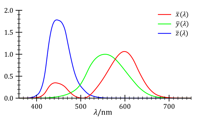
With these CMFs it is then possible to calculate the XYZ tri-stimulus responses as, for example: \begin{equation} X=\int_0^\infty F(\lambda)x(\lambda) d \lambda \end{equation} where F(λ) is the incident flux, x(λ) is the colour-matching function for the X-component, and similarly for the Y- and Z-components. The responses are then normalised such that X+Y+Z=1, and thus only two components need to be specified to complete describe the colour of the object. Once the tri-stimulus response XYZ has been determined in the XYZ colour space, it can be converted to different colour space via a linear transform. As noted before, the sRGB colour space is not quite as standard as we might hope, but in this work we have assumed: \begin{equation*} \begin{pmatrix} R \\ G \\ B \end{pmatrix} = \begin{pmatrix} 2.4934969 & -0.9313836 & -0.4027108 \\ -0.8294890 & 1.7626641 & 0.0236247 \\ 0.0358458 & -0.0761724 & 0.9568845 \end{pmatrix} \begin{pmatrix} X \\ Y \\ Z \end{pmatrix} \end{equation*} where the transformation matrix from XYZ to sRGB here has been taken from http://www.russellcottrell.com/photo/matrixCalculator.htm.