
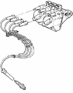
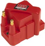
| 1. Ignition System |
Standard Lotus spark plug is a NGK EPR6EKN. The direct cross to the Denzo iridium plug is an (IW20). I have gone for a slightly cooler version the IW22.
|
 |
| 2. Fuel System |
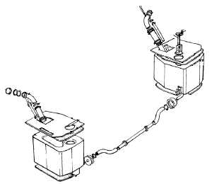
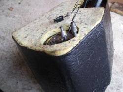
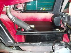
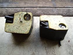
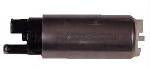
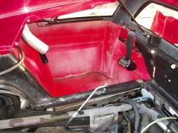
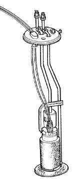
Sytec fuel pump. The standard S4 fuel pump is a roller vane type, high pressure electric fuel pump mounted within the right hand fuel tank. The pump supplies fuel at 30.5-55psi to the fuel rail. On the Sport 300 the fuel pump was upgraded to a higher capacity pump as fuel starvation was experienced in testing. Unfortunately the Sport 300 pump is now obsolete and so an alternative up rated delivery compatible in-tank pump was sourced. The Sytec pump chosen is able to support motors with over 400 hp.
Click to on image to enlarge
|
|
|
 |
 Click to on image to enlarge Click to on image to enlarge |
 |
 Click to on image to enlarge Click to on image to enlarge |
|
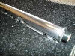
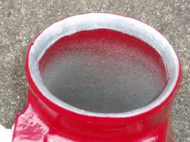
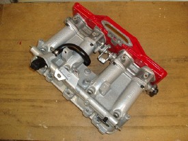
Fuel manifold. The aluminium fuel rail receives fuel at its forward end and
|
|
|
 |
|
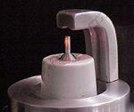
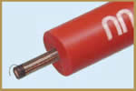
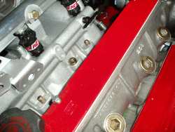
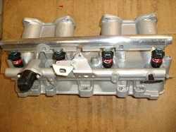
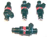
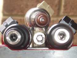
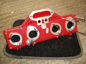
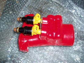
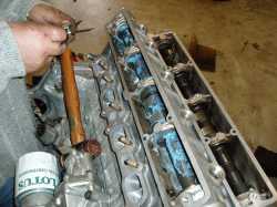
Fuel injectors _ Primary The stock primary injectors are low impedance (2 ohms) 370cc/min or 36lb/hr "peak and hold" injectors. The Lotus OEM ones have been frequently been deplored for their poor design and spray pattern. Blue-printed and matched primary fuel injectors were sourced from John Welch. They are 370 cc/mm RC Engineering injectors which are matched to a 1% tolerance flow rate. My advice is to upgrade the quality of the primary injectors but do not increase the flow rate. To increase the fuel delivery potential upgrade the secondary injectors Fuel injectors _ Secondary Although the two plenum secondary injectors are similar in construction to the primary injectors they are actually high impedance (16 ohm) 190 cc/min or 18 lb/hr saturated type injectors. These injectors operate at a fixed frequency of 128 Hz, with the quantity of fuel delivered dependent only the pulse width sent by the ECU. The stock S4 ECU fuel mapping only triggers the secondary injectors over 4800 rpm and 0.7 bar boost. I have fitted 270 cc/min (25.7 lb/hr) RC Racing high impedance injectors. If you are undertaking major engine mods it is very important to think about the correct fuelling. The ECU goes into "open loop" mode above 94% throttle openings, in open loop mode there is no feedback to the ECU from the lambda sensor, under these conditions fuelling is based on pre-stored fuel maps in the ECU. Picture on the right is an image of the 2 secondary RC injectors on the bottom compared to the standard Bosch injectors. RC Racing have a nice tool to work out the amount of fuel you require for a specific hp figure. Go to their technical section. |
 |
 |
 |
 |
 |
 |
 |
 |

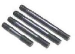 to 190,000 psi tensile strength, and precision J-form threads rolled after heat-treat to create a fastener so that it has threads 1000% stronger than others.
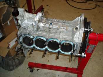
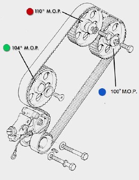 |
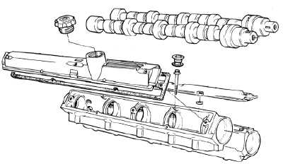
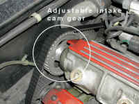
CAM GEAR SUMMARY by Tim Engel
Click to on image to enlarge
|
|||||||||||||||||||||||||||
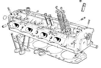
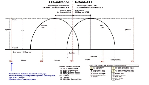
The cam timing 910 Turbo engines is RETARDED due to on emission constraints. The 910's 107-cam is designed to run with a 104 MOP (Maximum Opening Point) on both inlet and exhaust. On the more recent cars (1985 onwards) both cams are retarded. The details are summarised below: If the nominally correct MOP for the cam is 104° as is the case with the 107- cams in the Turbo-910 engine, then: 100 MOP = 4 degrees RETARD on the EXHAUST cam and 110 MOP = 6 degrees RETARD on the INTAKE cam. To achieve 104-104 cam timing on 1985-onward 910's with 110-100 timing, one more 104 pulley is required. However good gains can be achieved by just swapping the AUX, Green dot, 104 ° pulley for the inlet Red dot 110° pulley on the inlet cam shaft. Many thanks to Tim Engel. He is the real expert on Esprit timing matters and provided me with all this information. He has a excel workbook that allows you to look at different cam timings. It can be downloaded here. Tim has also compiled a comprehensive summary of all the cam data for the 9xx engine in an excel file that can be downloaded here. |
||||||||||||||||||||||||||||
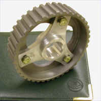
Once the variable cam gear is installed the cam timing can be varied within an 8 degree range within minutes. This allows you to easily revert to the stock US setting for emissions their more demanding testing requirements. Simply, loosen the 3 bolts on the cam gear and rotate the cam by a few degrees. Graduated degree markings on the gear allow you to adjust the timing precisely. |
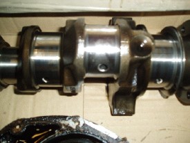
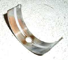
| 6. Crankshaft | |
|
When the engine was stripped we discovered that my crankshaft bearings were on their last legs, so new shells have been fitted. The crankshaft itself has been lightly polished, it did not need to be re-ground, so the standard size bearings were refitted. Crank shaft, flywheel, clutch assembly, pistons were all dynamically balanced and lightened by Steve Smith at Vibration Free. |
 |
 |
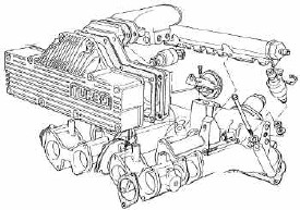
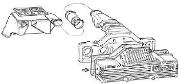
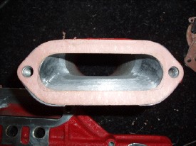
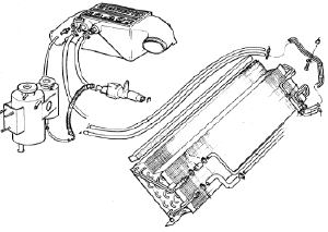
| 7. Chargecooler | The 4-cylinder models (SE, S4, S4s & GT3) use an air/water heat exchanger (chargecooler) to reduce the air inlet temperatures and so increase the density of air leaving the turbocharger compressor before it enters the intake plenum chamber. The chargecooler is flexibly mounted to the engine, and uses flexible high temperature hoses to connect the intake and outlet to the compressor and plenum respectively. Air passing through the chargecooler flows past a matrix of tubes through which water is circulated in a closed system by an engine driven pump. Heat is transferred from the intake charge air to the water which is pumped via alloy pipes routed through the chassis backbone, to a chargecooler radiator mounted ahead of both the air conditioning condenser and the engine cooling radiator. The system is prone to many problems and it is vital for the optimum performance of you car that this system is in tip top condition. LEW has written a very comprehensive article on Lotus Chargecooling, including a recent factory update relating to the chargecooler pump. The chargecooler system on my car has been extensively upgraded as detailed below. |
|
Click on Images To Enlarge |
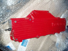
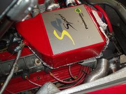
Double Size Chargecooler was one of my first every mods. Lowering the inlet air temperature is a very safe and easy way to increase engine performance. You gain approx 0.5 - 1 hp for every 1 °C you can lower the inlet air temperature.
|
|
|
 My tests indicate that the larger chargecooler does dramatically improve the air cooling efficiency rather than lowering the peak inlet temperatures.
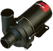
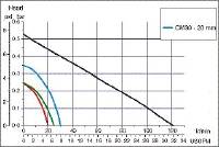
Electric Chargecooler Pump is in my view the best initial modification to upgrade your intercooling or chargecooling system. There are a number of pump options, I initially fitted the Craig Davies pump available from Demon Tweeks. However, I now use an 12 V magnetically driven marine specification pump with twice the pumping capacity. Pumps choices are covered by Kato's article on LEW and by John Welch. It is interesting to note that fitting of an electric chargecooler pump is now Lotus approved. |
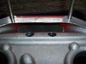
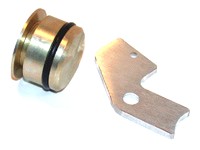
Chargecooler blanking plug is essential if you remove the mechanical chargecooler pump and fit an electric water pump. Otherwise you may experience a potentially fatal loss of oil pressure. Blanking plugs are available from WC Engineering. |
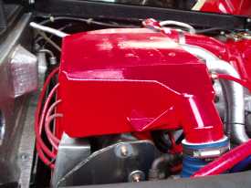
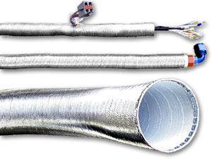
I have always been amazed by the fact that Lotus choose to locate the chargecooler on top of a hot engine and that the cool water return feed runs so close to the engine. Where ever possible these items have now been thermally insulated. See below for my effort to thermally insulate the chargecooler. |
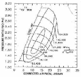
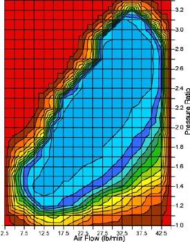
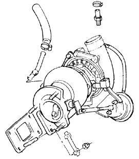
| 8. Turbocharger | The Esprit S4 is fitted with a Garrett Air Research T-3 turbo, standard oil bushings, 0.63 AR "Lotus only" turbine housing with integral wastegate, standard T-3 compressor housing, and a 42 trim compressor wheel, oil fed and water cooled. It has a maximum flow rating of 25 lbs/min at a pressure ratio of 2.2 (1.2 bar boost) with 58% efficiency (see compressor map below). To up the performance for the S4s, the Garrett T3 turbo was modified by fitting a 60 trim compressor wheel. It has a maximum flow rating of 34 lbs/min at a pressure ratio of 2.3 (1.3 bar boost) with 64% efficiency.
Stock Esprit S4 Turbo; T3-45 Compressor Map These air flow figures ultimately become the limiting factor if you want to make substantial gains in the performance of the engine. Even after you fit a higher performance chip often you cannot get any more sustained hp. The the physics of the turbo does not allow it !. The bottom line is that turning up the boost by fitting "a performance chip" to the stock S4 turbo quickly runs up against the fact that the stock turbo cannot flow enough air at the top end, the result is that the inlet temperature (MAT) raises very dramatically and boost drops away. In fact there is common condition in which increasing the boost will actually produce less power output. The turbine side can flow about 410 CFM of exhaust gases before the back pressure rises beyond acceptable limits. The engine can only make the stated 264 or 280 horsepower for about 6 seconds before these systems "catch up" with each other. Then, as the intake temp rises, the exhaust back pressure rises and the power falls away. John Welch at WC Engineering has written some fantastic articles on turbocharging Lotus Esprit's.
|
|
|
 |
|
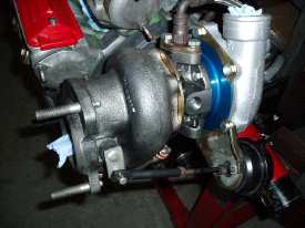 |
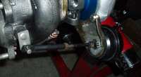
I have imported the WC Engineering, Stage 1 turbo shown on the left.Click to Enlarge Maximum Flow Optimum Flow |
 |
Ball bearing turbo's. The stock turbo centre section only has oiled "bushings" supporting the connecting shaft and there is quite a bit of drag associated with it. When using a ceramic ball bearing assembly in the centre section this parasitic drag is reduced down so low that it is negligible.
Benefits are:
WC Engineering assembles a modified turbine section with a machined compressor housing and a larger compressor wheel (larger than the S4s wheel) to produce a turbo that offers improved spool up response, more efficient boost with lower charge air temperatures, and a more free flowing turbine section.
The Compressor Flow Map for the WC Engineering Stage I Ceramic Ball Bearing Turbo is shown on the left. Maximum Flow Optimum Flow Power Output At maximum flow is 357 HP sustained with transient peaks around 375 HP.
|
 |
| 9. Heat Shields | |
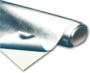
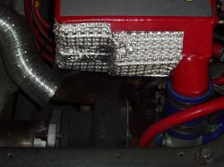
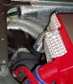
Nimbus GII heat shield produces a remarkably efficient thermal Thermal Conductivity @ 150 ºC = 0.27 W/mK |
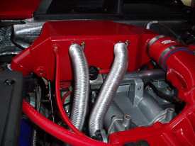
The 2 ply aluminium honeycomb sheet was cut to size and bent into the required shape and fitted underneath the chargecooler and around the turbocharger. I hope to see dramatic reduction in the radiated heat from the turbocharger heating the chargecooler matrix.
|
Click to enlarge
|
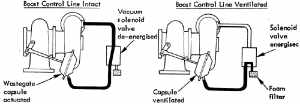
 to fit a stronger wastegate actuator. Otherwise the higher boost pressure may be bled-off by premature opening of the wastegate.
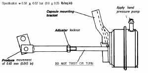
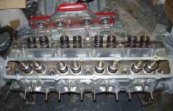
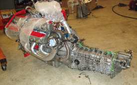
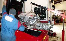
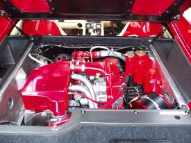
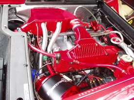
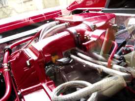
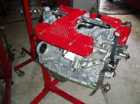
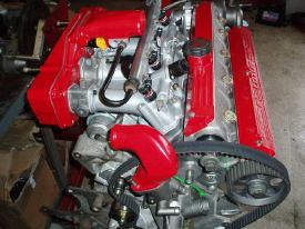
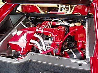
| 11. Assembled Engine and Gearbox | Images of the final stages of the engine build, Click on Images To Enlarge |
|
|
 |
 |
 |
 |
 |
Engine movie, click to play
DivX (.avi) Format
Acknowledgements
I would like to thank my very good friend Justin McAulay for all his help over the years.